5G Core Architecture
Hello everyone! 👋Welcome to "Bits and Bytes of Wireless".
🎯 Today's Topic: Exploring the 5G Technology Core Architecture.
Topics Covered
🌀 5G Core Network Functions
📡 5G Core Network Protocols
🎛️ 5G Network Slicing (NS)
☁️ 5G Core Network Deployment and Operations
5G System: High Level
This is the big picture of how 5G networks function to provide seamless connectivity and advanced services.
1. Key Components of the 5G System:
- UE (User Equipment):
- The end-user device, such as smartphones, IoT devices, or industrial equipment, connects to the 5G network.
- It communicates with the network through the radio part of 5G, called 5G NR (New Radio).
- NG-RAN (Next-Generation Radio Access Network):
- The gNB (5G Base Station) is a critical part of the NG-RAN and is responsible for wireless communication between the UE and the network.
- The New Radio (NR) supports features like higher frequencies, wider bandwidths, and advanced technologies like beamforming and massive MIMO.
- 5G Core Network:
- The brain of the 5G system, managing data routing, subscriber management, authentication, mobility, and session control.
- It acts as the bridge between the access network (NG-RAN) and the external data networks.
- Data Network (DN):
- External networks such as the internet, private enterprise networks, or application-specific networks where the actual data is sent or received.
2. The End-to-End Connection Flow:
- UE Device ↔ NG-RAN:
- The UE connects to the gNB in the NG-RAN via the air interface. This connection uses the 5G NR technology for high-speed, low-latency communication.
- NG-RAN ↔ 5G Core Network:
- The gNB forwards user and control plane traffic to the 5G Core Network, which processes, manages, and routes the data.
- 5G Core Network ↔ Data Network:
- The 5G Core acts as the intermediary between the mobile user and the internet or other private networks, ensuring secure and efficient data transfer.
3. Why This Architecture Matters:
- This architecture allows 5G to deliver its promised capabilities, such as ultra-reliable low-latency communication (URLLC), massive machine-type communications (mMTC), and enhanced mobile broadband (eMBB).
- The modular design separates radio access, core processing, and external data handling, providing flexibility for use cases like network slicing and dynamic resource allocation.
5G System Architecture
The 5G Core (5GC) is the central and most critical component of the 5G system. It connects the radio access network (RAN) to external data networks (e.g., the internet, private networks) and manages all essential operations required to deliver seamless connectivity, advanced services, and improved user experiences.
Key Functions of the 5G Core Network:
- User Session Management:
- Establishes, maintains, and terminates sessions for data transfer between the user equipment (UE) and the data network (DN).
- Ensures seamless session continuity even during handovers or mobility events.
- Mobility Management:
- Tracks and manages the location of the user across different network areas.
- Ensures uninterrupted service when users move across cell sites or geographic regions.
- Authentication and Security:
- Verifies the identity of users through secure methods like the Authentication Server Function (AUSF).
- Implements robust security measures to protect user data and network resources.
- Data Routing and Forwarding:
- Routes user traffic efficiently between the RAN and external data networks using the User Plane Function (UPF).
- Supports optimal traffic paths for low latency and high throughput.
PDU Sessions and QoS
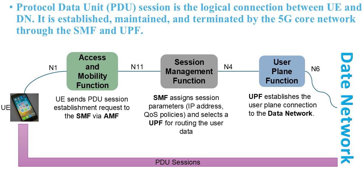
A PDU session is a logical connection between the UE and a Data Network (DN) in a 5G system. It provides a pathway for data transfer and supports different types of traffic.
Establishment Process:
- UE sends a PDU Session Establishment Request to the 5GC via the AMF.
- The Session Management Function (SMF) assigns session parameters (e.g., IP address, QoS policies).
- A User Plane Function (UPF) is selected for routing data.
PDU session key features:
- Mobility and Continuity, i.e., the user can have seamless handovers between gNBs or 5G base stations.
- And there will always be session continuity when moving across network slices or roaming scenarios.
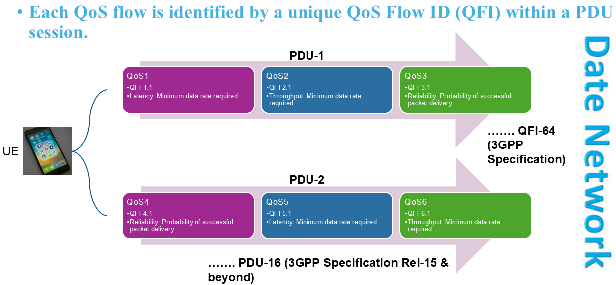
QoS Flow ID (QFI): A QoS Flow is the granularity level within a PDU session to manage the Quality of Service for specific types of traffic.
- Each QoS flow is identified by a unique QFI within a PDU session.
- Multiple QoS flows can exist in a single PDU session, differentiated by QFI values.
QoS Parameters are:
- Latency: Maximum delay acceptable.
- Throughput: Minimum data rate required.
- Reliability: Probability of successful packet delivery
- The number of PDU sessions and QoS flows that can occur between a User Equipment (UE) and a Data Network (DN) in a 5G system depends on several factors, including the network's capabilities, UE specifications, and the operator's configuration.
- A UE can establish up to 16 PDU sessions simultaneously with one or multiple Data Networks (DNs) according to 3GPP Specification (Rel-15 and beyond).
- A single PDU session can support up to 64 QoS flows.
Example Scenarios:
- A single UE could have:
- PDU Session 1: One PDU session for general internet (IPv4/IPv6 DN).
- PDU Session 2: Another PDU session for private enterprise Ethernet communication.
- PDU Session 3: Additional PDU sessions for IoT or specialized services.
- QoS Flows in PDU Session 1:
- QoS Flow 1: Streaming video (GBR).
- QoS Flow 2: Background app updates (Non-GBR).
5G Core: Access and Mobility Function (AMF)
Access and Mobility Management Function (AMF) operates as part of the Service-Based Architecture (SBA) to handle access and mobility management tasks for User Equipment (UE).
- Scenario 1: Suppose a UE powers on in a 5G network for the first time.
Process:
- UE scans for and connects to a gNB.
- It Sends a Registration Request to the AMF.
- The AMF Completes authentication, security setup, and registration.
- And then establishes PDU sessions for internet access.
- Scenario 2: The UE moves from one gNB to another within the same or a different AMF's service area.
Process:
- The UE is moving from one location to another, i.e., moving away from its current serving gNB to the vicinity of another gNB.
- The serving gNB initiates a handover request to the target gNB.
- The AMF updates the UE's location and routes signaling messages to the new gNB.
- The PDU session remains intact, with updated routing via the UPF.
AMF handles various critical aspects of UE connectivity and mobility management tasks.
1. Access Management: Manages the initial interaction between the UE and the network, ensuring secure and seamless connectivity.
- The UE sends a Registration Request to the AMF when it powers on.
- The AMF validates the UE's identity and capabilities, checking compatibility with the network.
- If the UE is authorized, the AMF responds with a Registration Accept message.
- The AMF coordinates authentication with the AUSF and retrieves subscription data from the UDM to ensure only authorized users access the network.
- If the UE moves between AMFs or networks, the registration process enables smooth transitions without losing connectivity.
2. Mobility management: Ensures the network keeps track of the UE’s location and suppots smooth transitions between cells and networks.
- The AMF tracks the UE's location using Tracking Areas (TAs).
- When the UE moves to a new TA, it sends a Tracking Area Update message to the AMF, ensuring its location is always up-to-date.
- For seamless mobility between 5G cells or RATs (e.g., between LTE and 5G):The serving gNB notifies the AMF of the handover.
- The AMF communicates with the target gNB and, if necessary, other AMFs.
- The session is handed over without interruption.
- For idle mode mobility, the AMF ensures the UE re-establishes connectivity upon resumption.
3. Slicing support: Matches UEs with the appropriate network slice based on their service requirements, enabling efficient resource utilization.
- During registration, the UE may request specific services that align with a network slice (e.g., enhanced mobile broadband or low-latency services).
- The AMF evaluates the UE's subscription and service requirements and assigns the most suitable slice using the NSSF (Network Slice Selection Function).
- If the UE's requirements change, the AMF can reassign it to a different slice dynamically.
4. Security Management: Protects the communication between the UE and the network, ensuring confidentiality, integrity, and authentication.
- After successful authentication, the AMF facilitates secure key exchanges between the UE and the network.
- These keys are used for encryption and integrity protection of both control and user-plane communications.
- The AMF also interacts with the AUSF to authenticate the UE and retrieve security credentials stored in the UDM.
- By leveraging SUCI (Subscription Concealed Identifier), the AMF ensures privacy for the UE's permanent identity (SUPI).
5. Connection Management: Manages signaling connections and provides a stable control interface for session management.
- The AMF establishes an RRC (Radio Resource Control) connection between the UE and the gNB.
- Maintains NAS signaling connections for tasks like authentication, mobility, and session management.
- Releases the connection when no longer needed, optimizing network resources.
- Interacts with the SMF (Session Management Function) to handle UE requests for PDU session establishment, modification, and termination.
- Coordinates QoS parameters and IP address assignment, ensuring that data sessions meet the UE's requirements.
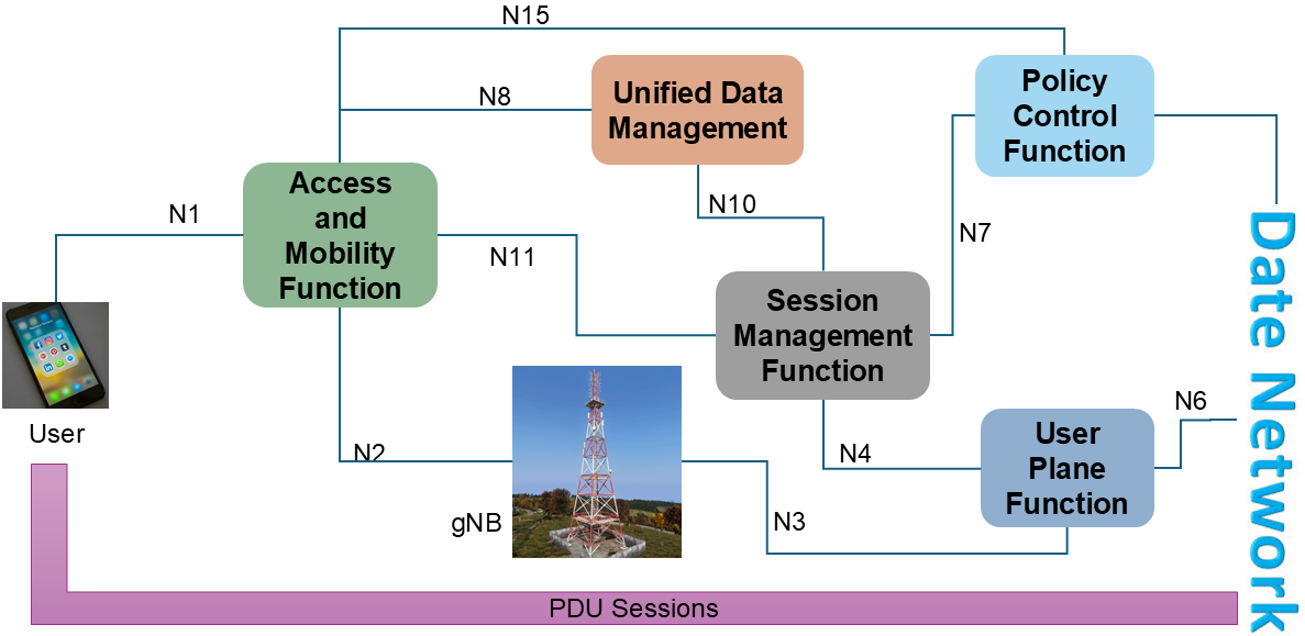
- N1 interface is between UE and AMF to carry signaling messages for UE registration, authentication, security, mobility, and session management.
- The UE sends a Registration Request over the N1 interface to the AMF.
- N2 Interface is for Communication between the RAN (gNB) and the AMF.
- Facilitates the exchange of signaling messages related to mobility, session setup, and policy enforcement. It also supports handover procedures between gNBs.
- N8 interface Retrieves subscription data such as authentication credentials, mobility restrictions, and policy information. Facilitates the storage and retrieval of UE context and subscription profiles.
- N10 interface is primarily for managing UE subscription and session-related data.
- UE Context Management involves managing the SMF's registration, modification, and deregistration for 3GPP and Non-3GPP access types. When the UE’s access type or subscription information changes, the SMF updates the UDM. The SMF informs the UDM when it no longer needs to manage a UE's session, freeing up resources.
- Subscriber Data management focuses on retrieving, subscribing to, or modifying UE subscription data managed by the UDM. It handles the Information on allowed network slices and mobility restrictions for a UE session. It also handles Data to assist in selecting the appropriate SMF for the UE. It also handles Information about the UE's active sessions stored in the SMF.
- N11 Interface Facilitates the establishment, modification, and termination of PDU sessions. It also Coordinates QoS policies and session parameters.


Comments
Post a Comment